Aeronautical Design Software
AAA is a comprehensive aircraft design program that gives users full authority over the entire preliminary design process. From weight and performance sizing to aerodynamics and stability and control analysis, you can monitor all aspects of the design every step of the way.


Advanced Aircraft Analysis Modules
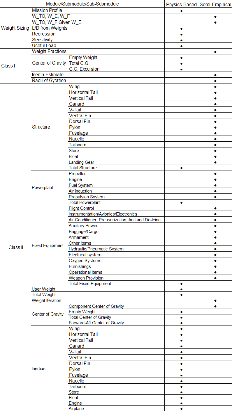
The purpose of the Weight Sizing module is to rapidly estimate the following weight components and/or sensitivity coefficients:
- Take-off weight, WTO
- Empty weight, WE
- Fuel weight, WF
- Sensitivity of take-off weight to aerodynamic, propulsion and mission parameters
These parameters are estimated on the basis of the following input:
- Mission specification.
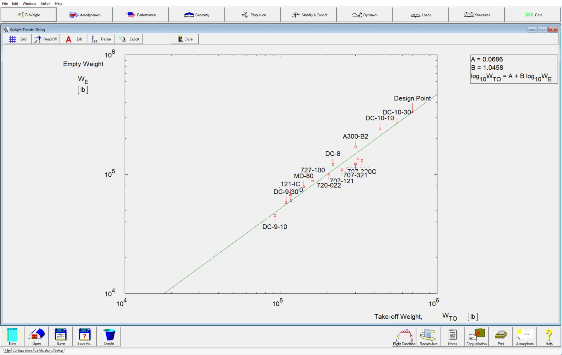
- Statistical relations between empty weight and take-off weight of existing similar aircraft. Methods to establish this statistical relationship for any type of aircraft are included in the AAA software.
The methods are based on Chapter 2, Sections 2.1 to 2.5 and Section 2.7 of Airplane Design Part I.
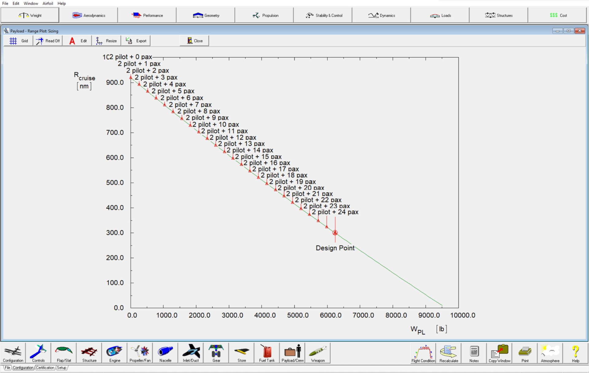
The weight sizing module contains a plot feature which displays the weight iteration process as well as a Class I payload-range diagram. This module also contains methods to calculate the lift-to-drag ratios for the climb, cruise, turn and loiter segments based on corresponding segment weights. This process iterates between the Weight Sizing module and Class I Drag module to converge on a solution for the take-off weight.
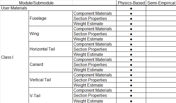
The purpose of this module is to estimate aircraft component weights and to determine whether or not the center of gravity of the aircraft is within the desirable range for different loading and unloading scenarios. The methods are based on Chapter 10 of Airplane Design Part II and Chapter 2 of Airplane Design Part V.
This module also contains the moments of inertia calculation, based on Chapter 3 of Airplane Design Part V. This option allows the user to estimate the moments of inertia of the aircraft with the radii of gyration method. The radii of gyration may be calculated from the moment of inertia data. The user can provide the data or the preloaded database can be used. The user has the option to select data from comparable aircraft. By selecting a category, a choice can be made between several available aircraft appearing in a table. Because the Class I inertia estimation is based on the selected aircraft, the user should choose the most comparable aircraft.
The purpose of this module is to present a Class II method for estimating aircraft component weights. The Class II estimation methods used in this module are based on those described in Airplane Design Part V. These methods employ empirical equations, which relate component weights to aircraft design characteristics. In the Class II weight estimate module, the weight estimation methods are identified as follows:
- Cessna method
- USAF method
- General Dynamics (GD) method
- Torenbeek method
- Vought method (Courtesy Daniel Raymer)
- DARcorporation method
Because aircraft component weight modeling in the software is a function of take-off weight, the Class II weight estimation module includes a weight iteration calculation which iterates between the take-off weights and component weights to converge on a solution.
Component Center of Gravity option allows the user to calculate the aircraft center of gravity by entering weight components and their locations in a preformatted table. Tables are available for structure weight, fixed equipment weight, powerplant weight and total weight. Center of gravity of wing, canard, horizontal tail, vertical tail, V-tail, fuselage, tailbooms, nacelles, stores, floats and ventral fins are calculated. These are based on geometry of the components and on the methods described in Chapter 8 of Airplane Design Part V.
Detailed center of gravity calculations based on empty weight and various loading scenarios are included in the software. These calculations include the determination of the most forward and most aft center of gravity based on the minimum and maximum weights of passengers, fuel, baggage, cargo etc. and the total center of gravity based on a specific loading scenario. The software includes the option to plot the C.G. envelope based on all possible loading scenarios. The plot feature can also be used to plot the empty weight C.G. along with the empty weight component’s C.G. together with a side view of the aircraft.
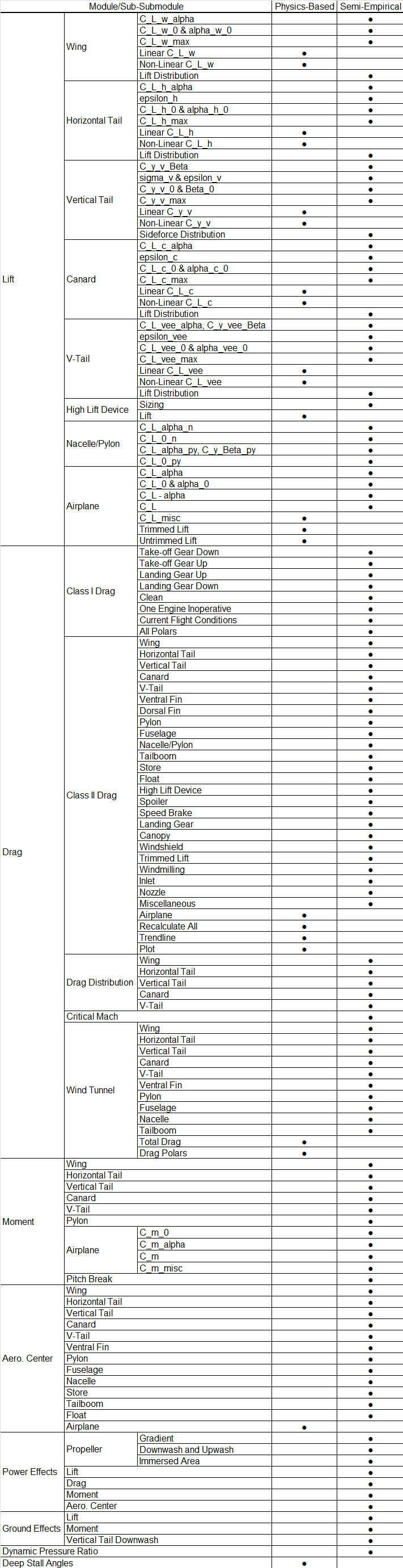
The Lift submodule can be used for estimating the lifting characteristics of aircraft lifting surfaces and high lift devices. Maximum lift coefficients for airfoils and wing, horizontal tail, vertical tail, V-tail and canard are calculated. The increase in the maximum lift coefficients caused by multiple high lift device segments is calculated. The user can define multiple unique segments of high lift devices on the wing. The user can select from the following list of high lift devices.
- Slats
- Krueger Flaps
- Drooped Ailerons/Elevons
- Plain Flaps
- Split Flaps
- Single-Slotted Flaps
- Type I Double-Slotted Flaps
- Type II Double-Slotted Flaps
- Fowler Flaps
- Triple-Slotted Flaps
The size of the trailing edge flap segment needed to meet the desired maximum lift coefficient for take-off and landing conditions can be calculated. The plotting feature can be used to plot the high lift device maximum lift coefficient as a function of flap deflection and flap chord ratio. The methods are based on Chapter 7 of Airplane Design Part II. The methodology used to determine the lifting surface spanwise lift distribution is based on lifting line theory.
Lift as a function of angle of attack, elevator (canardvator, ruddervator) and horizontal tail (canard, V-tail) incidence can be calculated.
The lift coefficient at zero-angle-of-attack can be used to determine the lift coefficients, downwash angle and upwash angle at zero aircraft angle of attack and the zero lift angle of attack. This module includes flap effects. The methods are described in Chapter 8 of Airplane Design Part VI.
Furthermore, the effect of body width on lift curve slope may also be calculated.
The Class I Drag submodule can be used for a first estimate of the aircraft drag. The Class I Drag module has the following seven options:
- Flaps in take-off configuration with gear down
- Flaps in take-off configuration with gear up
- No flap deflection and gear up
- Flaps in landing configuration with gear up
- Flaps in landing configuration with gear down
- One engine inoperative configuration
- Current aircraft flight condition
The program will check to see if the aircraft has retractable or fixed landing gear. All drag polars may be displayed at once: Gear Up, Gear Down, Flaps Up, Flaps Down, One Engine Inoperative and Current Condition. The methodology used to calculate the drag polar can be found in Chapter 3 of Airplane Design Part I. The Class I Drag module relates the total aircraft lift coefficient to the total aircraft drag coefficient by a parabolic drag polar equation.
An iteration is built-in to calculate take-off weight based on L/D derived from the Class I drag polar.
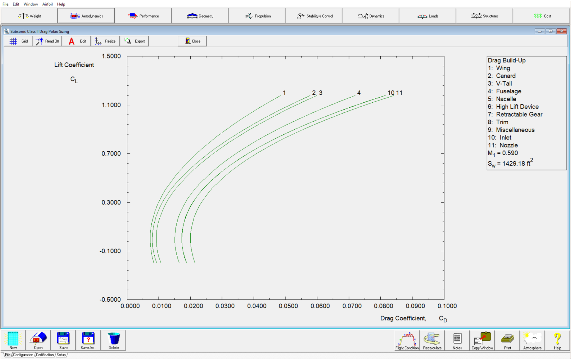
The purpose of the Class II Drag submodule is to supply a Class II method for predicting drag polars of aircraft during the preliminary design phase. A detailed drag polar can be calculated for the subsonic, transonic and supersonic flow regimes. The following drag calculations can be performed:
- Wing drag coefficient
- Horizontal tail drag coefficient
- Vertical tail drag coefficient
- Canard drag coefficient
- V-tail drag coefficient
- Ventral Fin drag coefficient
- Dorsal Fin drag coefficient
- Pylon drag coefficient
- Fuselage drag coefficient
- Nacelle drag coefficient
- Tailboom drag coefficient
- Store drag coefficient
- Float drag coefficient
- External fuel tank drag coefficient
- External weapon drag coefficient
- High lift device drag coefficient
- Spoiler drag coefficient
- Speed brake drag coefficient
- Landing gear drag coefficient
- Canopy drag coefficient
- Windshield drag coefficient
- Trim drag coefficient
- Drag coefficient due to windmilling
- Inlet drag coefficient
- Exhaust nozzle drag coefficient
- Miscellaneous drag coefficient
- Total aircraft drag coefficients
The program will account for fuselage base area change as a function of inoperative engines. Changes in nacelle drag are also accounted for due to inoperative engines. Dihedral is accounted for in the wetted areas of lifting surfaces.
The methods are based on Chapter 4 of Airplane Design Part VI.
The drag coefficient can be plotted as a function of lift coefficient, Mach number, flap deflection and as a component build‑up. Drag can also be plotted as a function of angle of attack for an untrimmed aircraft. The drag polar can be approximated with a trendline.
The Moment submodule calculates the spanwise moment distribution on the wing, horizontal tail, vertical tail and canard. The ground effects on aircraft moment are also determined. Methods are based on Airplane Design Part VI.
Moment as function of angle of attack, elevator (canardvator) and horizontal tail (canard) incidence can be calculated.
This pitching moment at zero-angle-of-attack submodule can be used to determine the zero lift aircraft pitching moment coefficients and pitching moment coefficients at zero aircraft angle of attack. This module includes flap effects. To account for each aircraft component, the pitching moment coefficient components are calculated separately. The user can estimate the zero lift pitching moment coefficient, the effect of trailing and leading edge flaps on lift and pitching moment coefficients. The methods are described in Chapter 8 of Airplane Design Part VI.
The Aerodynamic Center submodule can be used to calculate aerodynamic center locations of individual aircraft components and the aerodynamic center shift due to components. The aerodynamic center methods described are found in Airplane Design Part VI.
The aerodynamic center and shift can be calculated for the following components:
- Wing
- Horizontal Tail
- Vertical Tail
- Canard
- V-Tail
- Ventral Fin
- Pylon
- Fuselage
- Nacelle
- Tailboom
- Store
- Float
- External Fuel Tank
- External Weapon
- Aircraft
The aircraft aerodynamic center can be plotted with the C.G.’s.
The Dynamic Pressure Ratio module allows the user to predict the horizontal tail, V-tail and vertical tail dynamic pressure ratio as a variation of angle of attack. The wake effects are also accounted for in these calculations.
The purpose of the Power Effects module is to calculate the effects of the operating propeller on aerodynamic properties of the aircraft. The effects of power are calculated for the following parameters:
- Horizontal Tail downwash angle
- V-Tail downwash angle
- Dynamic Pressure ratio
- Lift and Pitching Moment coefficients
- Drag due to power
- Aerodynamic Center due to power
Power Effects can be applied to both single and multi-engine propeller driven aircraft.
The Pitch Break module uses the wing aspect ratio and wing quarter chord sweep angle to determine whether the pitch break is stable or unstable based on Figure 8.101 in Airplane Design Part VI.
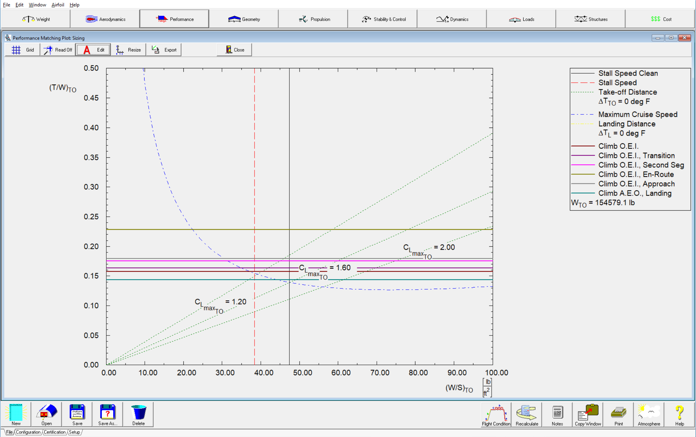
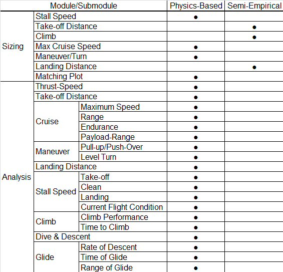
The purpose of the Performance Sizing module is to allow for a rapid estimation of those aircraft design parameters which have a major impact on aircraft performance. Aircraft are usually required to meet performance objectives in different categories depending on the mission profile. Meeting these performance objectives normally results in the determination of a range of values for:
- Wing loading (W/S)
- Thrust loading (T/W) or power loading (W/P)
- Aircraft maximum lift coefficients
The variables listed above are plotted in the form of a performance-matching plot. These plots depend on the type of aircraft, the applicable specification and the applicable regulation(s). With the help of such a plot, the combination of the highest possible wing loading and the smallest possible thrust (or highest power) loading, which meets all performance requirements, can be determined. The methodology used for performance sizing can be found in Airplane Design Part I.
The purpose of the Analysis submodule is to provide the user with Class II analysis methods for predicting the performance characteristics of an aircraft. The methodology used to analyze the performance characteristics can be found in Chapter 5 of Airplane Design Part VII and Airplane Aerodynamics and Performance.
The performance characteristics consists of:
- Thrust-Speed
- Power-Speed
- Stall Speed
- Take-off Distance
- Climb
- Cruise
- Dive and Descent
- Maneuver
- Glide
- Landing Distance
The engine performance data such as thrust or power can be entered as function of speed.
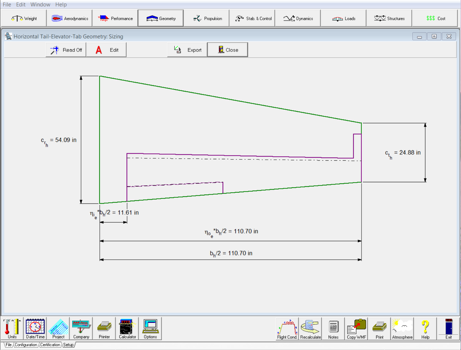
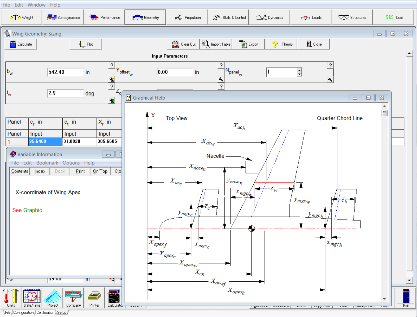
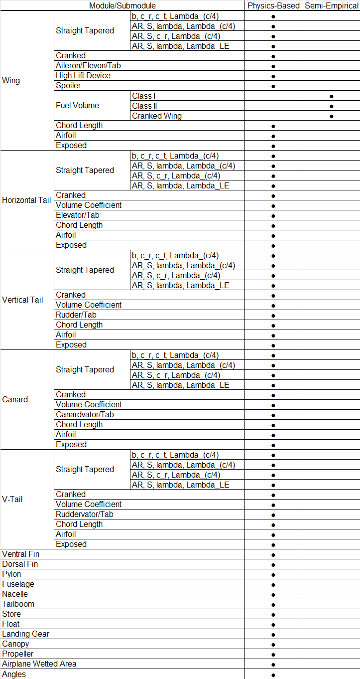
The purpose of the geometry module is to help the user define the geometry of the fuselage, wing, horizontal tail, vertical tail, V-tail and canard and calculate related parameters. The methodology used to calculate the aircraft component geometries is described in Airplane Design Part II. Two-dimensional geometry can be defined for straight and cranked lifting surfaces. For cranked lifting surfaces, an equivalent lifting surface defined by the fixing the tip or the mean geometric chord is generated. The fuel volume in the wing is calculated using Class I and Class II methods and accounts for fuel in cranked wings. For the horizontal tail, vertical tail, V-tail and canard the volume coefficient can be calculated. The control surfaces along with the corresponding lifting surfaces can be plotted. The chord length, airfoil thickness ratio and twist of any lifting surface at a specified spanwise station can be determined.
The fuselage module shows all cross-sections of the fuselage and is used to determine fuselage camber, inclination angles of each segment and cross-sectional area distribution.
The chord length at a specified surface chord station can be determined.
Other bodies such as nacelles, inlets/ducts, tailbooms, stores, floats, fuel tanks and weapons can also be defined in the same manner and have the same layout as the fuselage module.
There are also modules to define canopy, propeller and engine geometry.
The landing gear option allows the user to calculate the lateral angle between the aircraft center of gravity and the landing gear. This angle is useful in determining the risk of lateral tip-over on the ground.
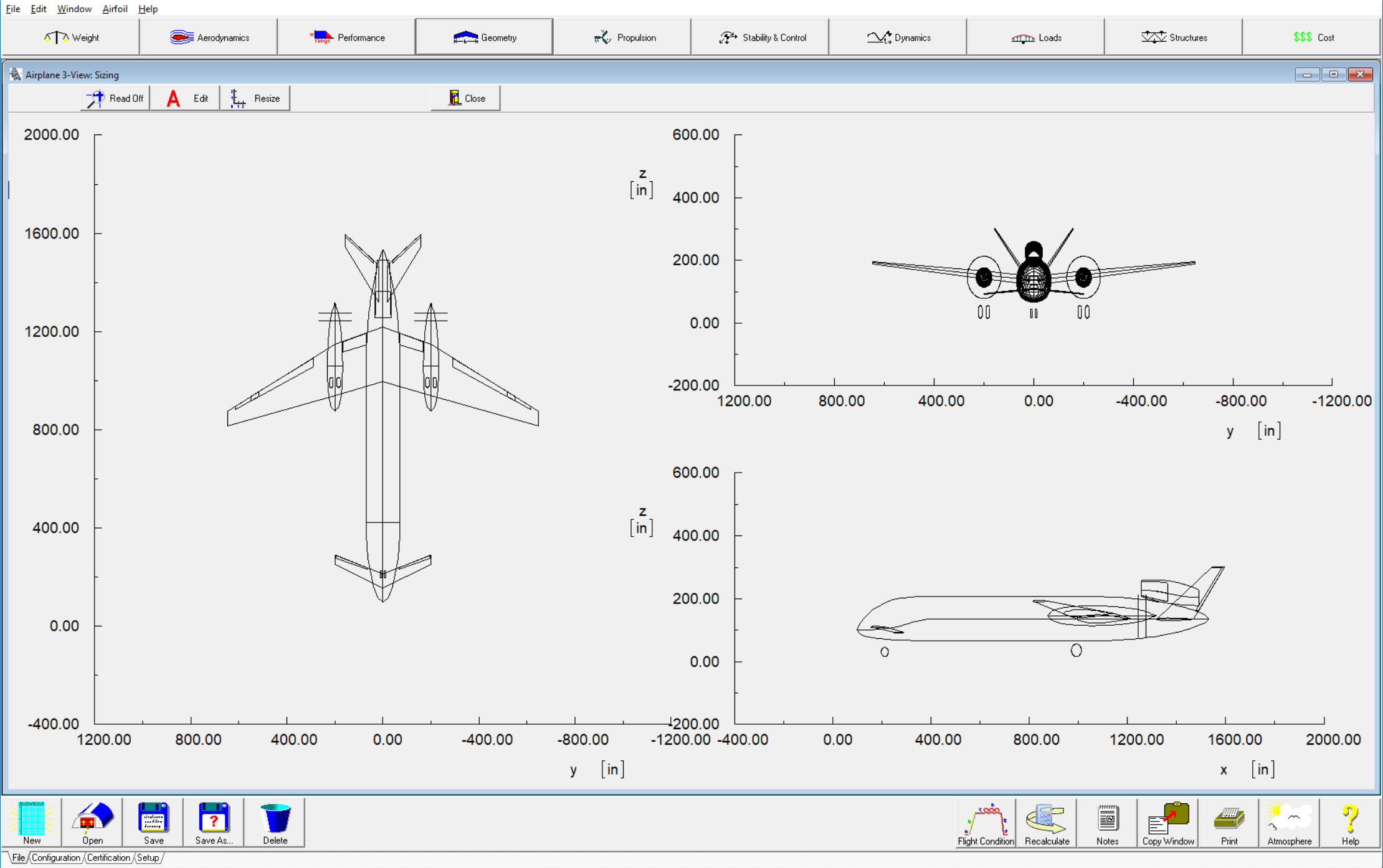
A three-view of the aircraft can be shown in the three-view module of the software. Different components can be selected to show in the three-view.
The aircraft geometry can be exported to CAD programs that use AeroPack (SharkCAD Pro). From SharkCAD Pro software, the geometry can be exported using several formats like STP, STL, DWG, DXF etc. The software allows the user to scale all the geometric parameters. For example, the geometric parameters can be scaled down to generate a smaller sized model suitable for wind tunnel testing.
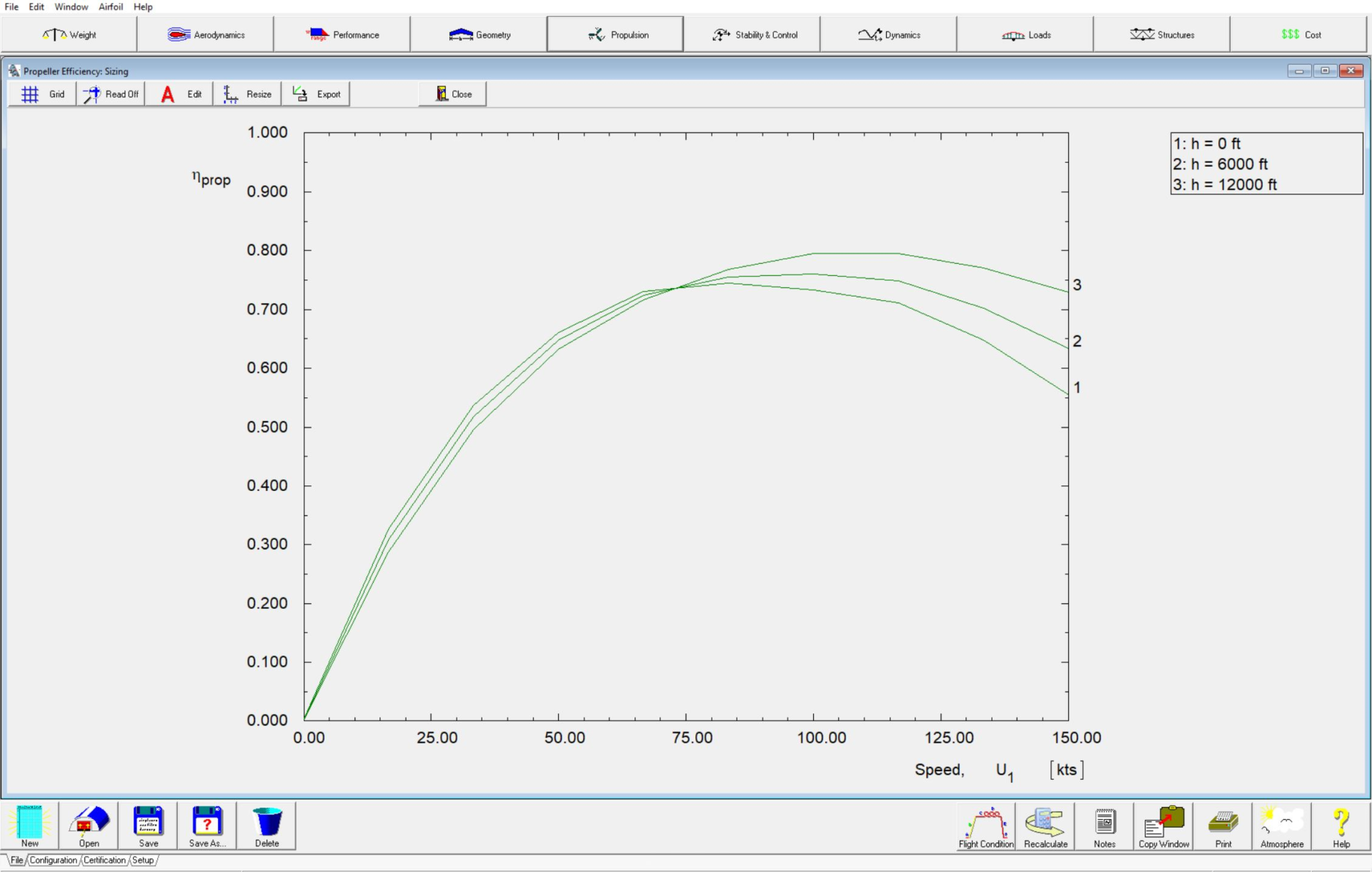
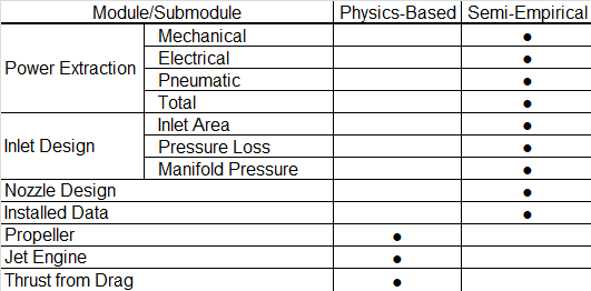
In this module the installed power and/or thrust of the aircraft can be calculated. Power extraction is also accounted for. The methods are valid for piston engines, electric engines, jet engines, turboprop and propfan engines. Calculations in this module are based on the methodologies outlined in Chapter 6 of Airplane Design Part VI.
Propeller performance maps can be imported into the propeller module to determine the propeller performance at various flight conditions. Installed thrust or power can be calculated from uninstalled engine and propeller performance.
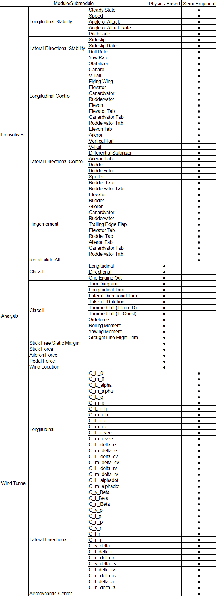
The purpose of the Derivatives submodule is to compute the non-dimensional aerodynamic coefficients, stability and control derivatives for a rigid aircraft in a given flight condition (i.e., for a given weight, altitude and speed and C.G. location). The derivatives module consists of longitudinal stability derivatives, lateral-directional stability derivatives, longitudinal control derivatives and lateral-directional control derivatives. The derivatives can be calculated for tail aft, canard, three-surface configurations and flying wing.
For longitudinal stability derivatives the following options are available:
- Steady state lift, drag, moment and thrust coefficients
- Speed derivatives
- Angle of attack derivatives
- Rate of angle of attack derivatives
- Pitch rate derivatives
For lateral-directional stability derivatives the following options are available:
- Angle-of-sideslip derivatives
- Rate of angle-of-sideslip derivatives
- Roll rate derivatives
- Yaw rate derivatives
For longitudinal control derivatives the following options are available:
- Stabilizer control derivatives
- Elevator control derivatives
- Elevator tab control derivatives
- Canard control derivatives
- Canardvator control derivatives
- Canardvator tab control derivatives
- V-tail control derivatives
- Ruddervator control derivatives
- Ruddervator tab control derivatives
- Flying wing control derivatives
- Elevon control derivatives
- Elevon tab-control derivatives
For lateral-directional control derivatives the following options are available:
- Aileron derivatives
- Aileron tab derivatives
- Spoiler derivatives
- Vertical tail derivatives
- Rudder derivatives
- Rudder tab derivatives
- V-tail derivatives
- Ruddervator derivatives
- Ruddervator tab derivatives
- Differential stabilizer derivatives
- Elevon derivatives
- Elevon tab derivatives
The hingemoment submodule is used to determine the hingemoment coefficient derivatives of the elevator, elevator tab, rudder, rudder tab, aileron, aileron tab, canardvator, canardvator tab, ruddervator, ruddervator tab, elevon, elevon tab and trailing edge flap. The control surfaces can have unshielded, fully shielded and partially shielded horn balances. The methodology for the hingemoment calculations is found in Airplane Design Part VI.
The methodology used to analyze the Stability and Control characteristics can be found in Chapter 11 of Airplane Design Part II. This module includes longitudinal stability and empennage sizing, directional stability and empennage sizing and minimum control speed with one engine inoperative stability/empennage sizing.
Inputs are simplified and choice is given between geometric volume coefficient or volume coefficient based on C.G. and A.C.
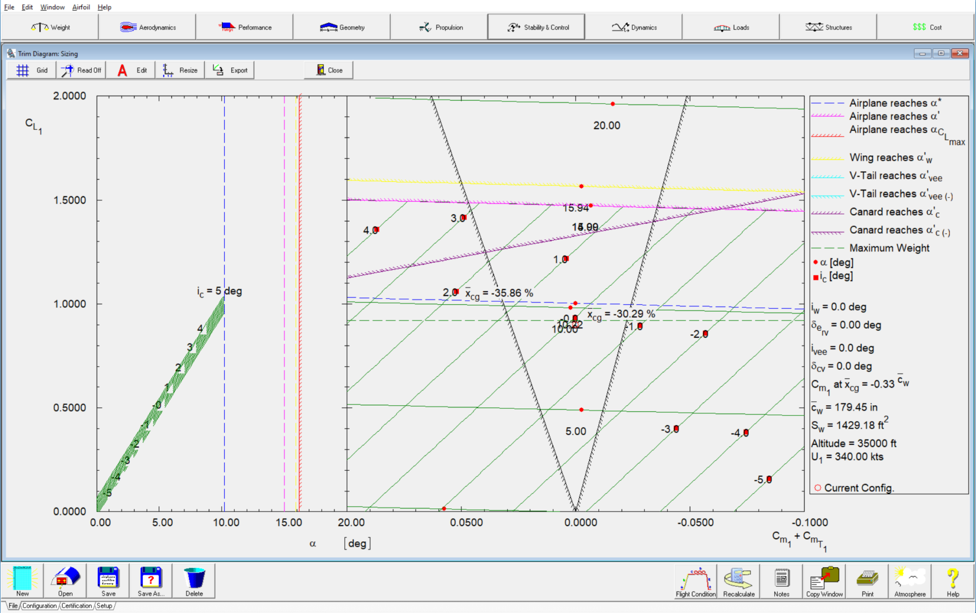
The methodology used to analyze the longitudinal and lateral-directional trim characteristics can be found in Chapter 5 of Flight Dynamics Part I.
The Class II methods consist of trim diagram, longitudinal trim and lateral-directional trim. The elevator stick (or control wheel) forces, aileron stick (or control wheel) forces and rudder pedal forces can be calculated. The trim diagram determines control deflections and angles of attack for different center of gravity locations to trim the aircraft longitudinally. Trim diagrams include propeller power effects.
Other important stability and control characteristics such as take-off rotation and a variety of dynamic stability considerations are calculated that are not covered by the Class I method.
Effect of wing location variation on stability and center of gravity range is analyzed and plotted.
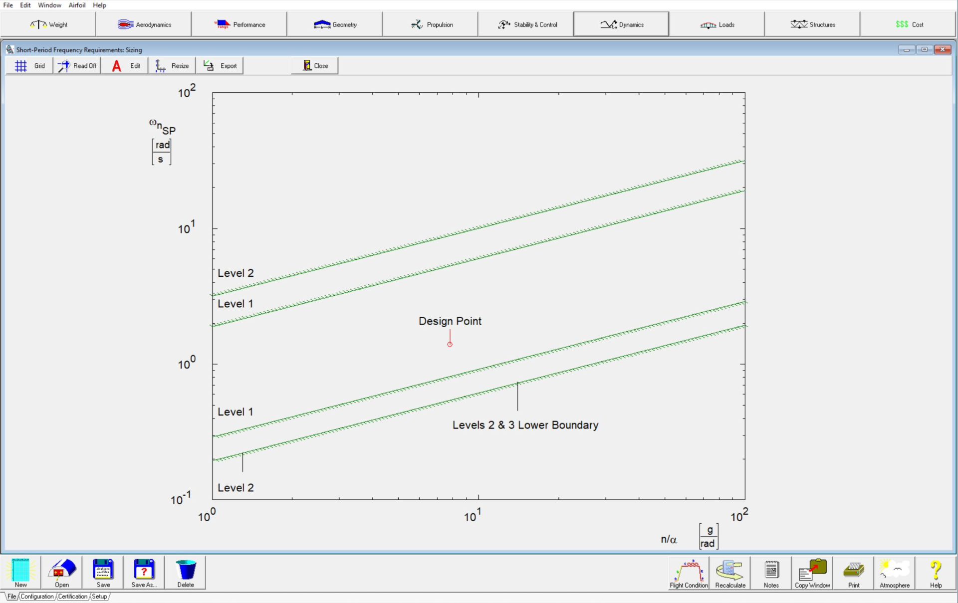
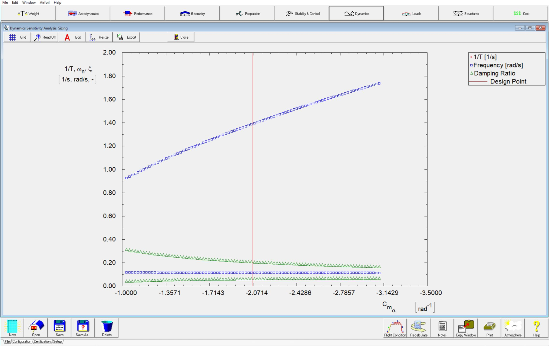
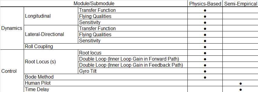
The purpose of the dynamics module is to help the user analyze the open loop dynamic characteristics of the aircraft in a given flight condition. The methodology used to analyze open loop dynamic characteristics can be found in Flight Dynamics Part I.
Dynamics is divided into estimation of the longitudinal and lateral-directional dynamic characteristics. Aircraft transfer functions are determined. Flying qualities are checked against civil and military requirements. The effect of roll-pitch yaw coupling effect on the dynamic analysis is also determined. Sensitivity of various stability and control derivatives on flying qualities is also established. Phugoid and short period are determined. Spiral, dutch roll and roll performance are investigated.
The Routh-Hurwitz stability requirements are calculated.
The purpose of the Control module is to help the user analyze single and double loop feedback control systems of the aircraft. If the open loop dynamic characteristics of the aircraft are known, root locus analyses may be performed in the S-plane. The control analysis submodule can also be used to analyze a system open loop transfer function in the frequency domain (Bode diagram). The methodology used to analyze feedback control systems can be found in Airplane Flight Dynamics Part II.
The transfer functions can be selected from the standard aircraft transfer functions or defined by the user. If the longitudinal and lateral-directional stability derivatives of the aircraft are known, the user may use the Dynamics module prior to using the Control analysis module to generate the longitudinal and lateral-directional dynamic transfer functions of the aircraft. These transfer functions are transferred into the Control analysis module and can only be generated in the Dynamics module.
The transfer functions are:
- Speed-to-Elevator
- Angle-of-Attack-to-V-Tail
- Pitch-Angle-to-Canard
- Angle-of-Attack-to-Elevator
- Pitch-Angle-to-V-Tail
- Angle-of-Attack-to-Canardvator
- Pitch-Angle-to-Elevator
- Speed-to-Elevon
- Human Pilot
- Speed-to-Ruddervator
- Angle-of-Attack-to-Elevon
- Sideslip-Angle-to-Aileron
- Angle-of-Attack-to-Ruddervator
- Pitch-Angle-to-Elevon
- Bank-Angle-to-Aileron
- Pitch-Angle-to- Ruddervator
- Speed-to-Canardvator
- Heading-Angle-to-Aileron
- Speed-to-Stabilizer
- Angle-of-Attack-to-Canardvator
- Sideslip-Angle-to-Rudder
- Angle-of-Attack-to-Stabilizer
- Pitch-Angle-to-Canardvator
- Bank-Angle-to-Rudder
- Pitch-Angle-to-Stabilizer
- Speed-to-Canard
- Heading-Angle-to-Rudder
- Speed-to-V-Tail
- Angle-of-Attack-to-Canard
- Defined by the user
The following control systems can be analyzed:
- Single loop feedback
- Double loop control systems with the inner loop gain in the forward path
- Double loop control systems with the inner loop gain in the feedback path
- Gyro tilt angle effect
The human pilot calculation can be used to estimate a human pilot transfer function for use in the open loop control system analysis. The human pilot module can be used to model pilots of differing abilities, reaction times and physical fitness. This module can even be used to show the dangers of a drunken pilot in the loop. The methodology used to analyze a human pilot transfer function can be found in Chapter 10 of Airplane Flight Dynamics Part II.
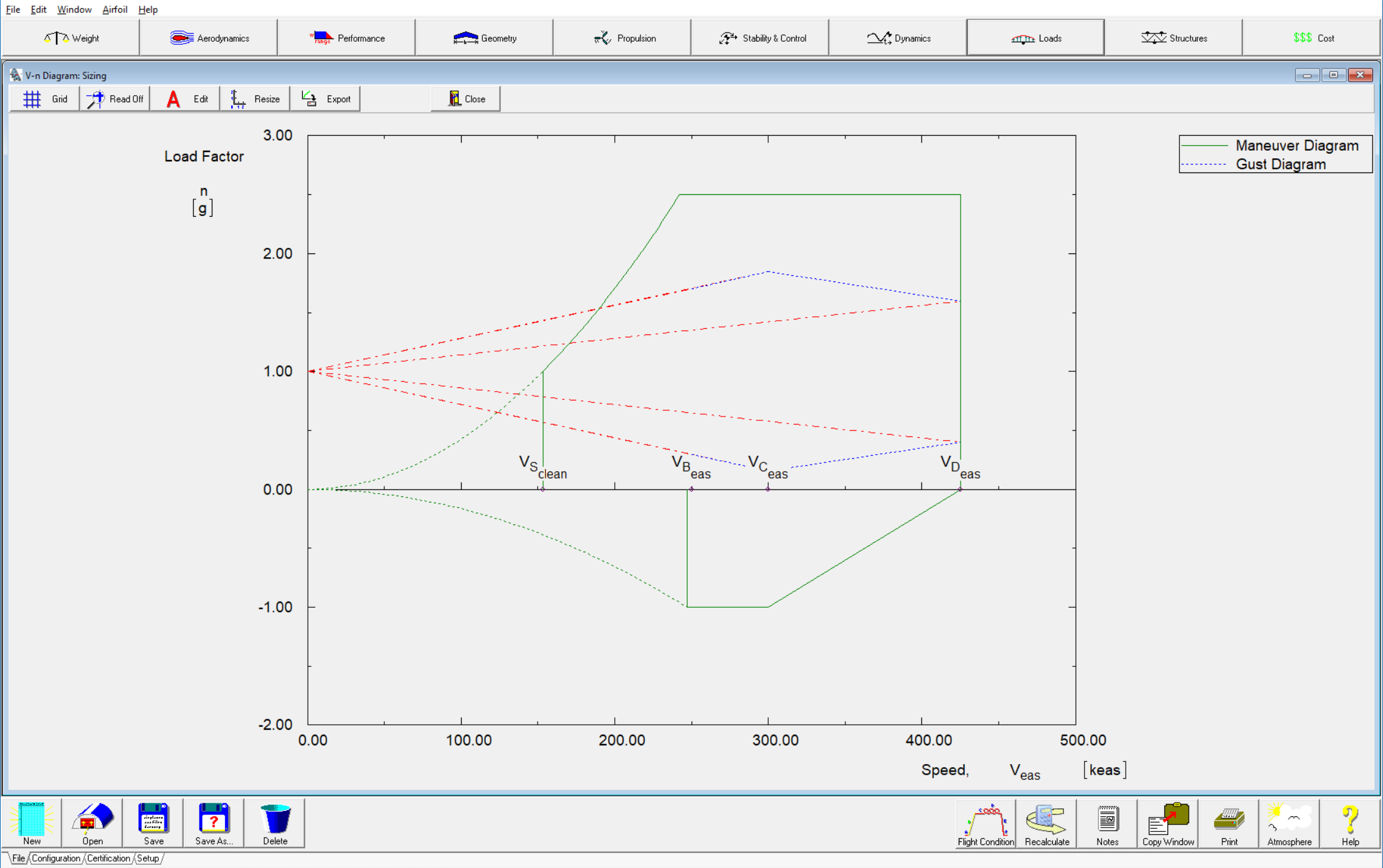
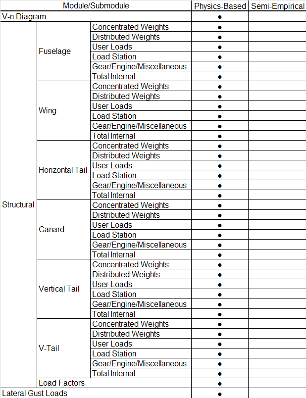
The purpose of this module is to estimate loads placed on aircraft components and to determine important information for structural design and sizing. The Loads module consists of three submodules: V-n Diagram, Structural Loads and Lateral Gust Loads. The purpose of the V-n Diagram submodule is to determine load factors and their corresponding speeds. The purpose of the Structural Loads submodule is to calculate the internal forces and moments in the structural components of an aircraft. Use of the Loads module options will be described in the following sections.
In this submodule, velocity vs. load factor (V-n) diagrams can be constructed for the following types of aircraft: FAR 23 certified, FAR 25 certified and MIL-A-8861(ASG) certified aircraft.
In this submodule the total internal loads for each structural component can be calculated in any combination that the user desires.
The following options are available to calculate the loads acting on a structural component:
- Structural loads on the fuselage
- Structural loads on the wing
- Structural loads on the horizontal tail
- Structural loads on the canard
- Structural loads on the vertical tail
- Structural loads on the V-tail
- Estimation of the accelerations and rates acting on the aircraft. Before the total internal loads for any structural component can be calculated, the linear accelerations, angular accelerations and angular rates must be calculated using this option.
In this submodule, the lateral gust loads for different speeds can be calculated.
AAA Benefits
Tested & Verified Commercial Software Product
Over
Over
Over
SAVES TIME
SAVES MONEY
You will spend more in a two-month period developing your own in-house code, in man-hour cost alone, than if you purchased one commercial license of AAA. You will save over 80% in man-hour costs using AAA for preliminary design, versus using handbook and spreadsheet calculations.
REDUCES ERRORS
Using AAA will greatly reduce calculation errors. Being able to use multiple flight conditions (forward c.g., aft c.g., low speed, high speed, flaps up, flaps down, etc.) is a unique feature of AAA and significantly reduces time to track data and prevent potential errors.
KEEPS IMPROVING
We use AAA for our aircraft design consulting services. We are constantly updating and refining the methods used, based on our research and wind tunnel tests that we perform. This leads to regular software version updates, which benefits all of our software clients.
Support Documents & Downloads
Software License Pricing
Software purchase includes 12 months software maintenance (tech support, service releases and new version upgrades). Delivery: Software download link and CmActLicense file via email.
System Requirements
OS: Windows (32/64 bit) 10 and up – Minimum Free Hard Disk Space: 160 MB – Minimum Screen Resolution: 1024 x 768
Software Licensing
DARcorporation uses the Wibu-Systems CodeMeter technology for the software licensing. CodeMeter stores the software license securely in a CmActLicense, a computer-bound license file, or a CmDongle, hardware-based security.
The CodeMeter license can be installed on a server (for multiple user access) or individual computer. CodeMeter license cannot be transferred to another computer once the license is installed. If you wish to transfer your CodeMeter license to different computers, a USB CodeMeter CmDongle is available for $500.00.
For more details, please visit Wibu-Systems CodeMeter website.
System Requirements
OS: Windows (32/64 bit) 10 and up
Minimum Free Hard Disk Space: 160 MB
Minimum Screen Resolution: 1024 x 768
Software Documentation
- AAA 5.1 User Manual (PDF)
- AAA 5.0 User Manual (PDF)
- AAA 4.0 User Manual (Kindle)
- AAA 4.0 User Manual (Print)
- Software License Agreement
- AAA University Labs
- AAA Case Studies
New & Upgrade Installation:
Free Downloads!
AAA Reader is a standalone program that allows users without AAA to view data stored in AAA files.
AAA Examples include over 60+ AAA aircraft files that can be read using AAA or AAA Reader.
AAA Atmosphere Module can be used to calculate the Mach number, Reynolds number, Temperature, Kinematic Viscosity, Density, Dynamic Pressure and speed of sound along with density, pressure and temperature ratios at various altitudes and speeds.
AAA Tips of the Day is the complete list of AAA tips that appear when the software starts. These tips offer hot key combinations, short cuts and more to enhance your user experience.
Windows Patches for AAA Help System
Windows 11 and 10 Patches
- Download winhlp32 zip file.
- Unzip the files to a local folder of your choice, right-click on install.cmd and select Run as administrator.
- The install batch file should install the needed winhlp32.exe to your operating system.
- Link to Microsoft for manual fix (look under “Manually enable macros on a single computer”)
Windows 8.1 Patches
- Download WIN-8.1 Patch One
- Link to Microsoft for manual fix (look under “Manually enable macros on a single computer”)
Windows 8 Patches
- Download WIN-8 Patch One
- Link to Microsoft for manual fix (look under “Manually enable macros on a single computer”)
Windows 7 Patches
AAA Geometry Import Files
To simplify the process of inputting body geometry (e.g. fuselage, nacelles, tailbooms, stores and floats) into AAA, we are making available an AAA Body Geometry Import file. We use this spreadsheet in-house to quickly organize our body geometry data so that it can be easily imported into AAA. Download Import File & Instructions Below:
Watch How to Input Fuselage Geometry from CAD to see how this file is used:
To expedite the AAA modeling process, we have made common fuselage and nacelle geometry import files available for download. These files can be used to quickly model common fuselage and nacelle geometry so that you can jump right into the iterative process of airplane design. Once your design has progressed you can customize these geometries to suit the unique appearance and performance requirements of your airplane.
Watch How to Input Fuselage Geometry from AAA Import Files to see how this file is used:
Fuselage Imports
Nacelle Imports
OUR CUSTOMERS
From Over 50 Countries
AAA is an industry standard aircraft design, stability and control analysis software and is installed in over 50 countries and is used by major aeronautical engineering universities, aircraft manufacturers and military organizations worldwide!